Can Vapor Chamber be combined with heat sinks?
Vapor chamber often promises great heat spreading. Many engineers wonder if it can work well with old‑school fins and heat sinks. This question can matter for big thermal loads.
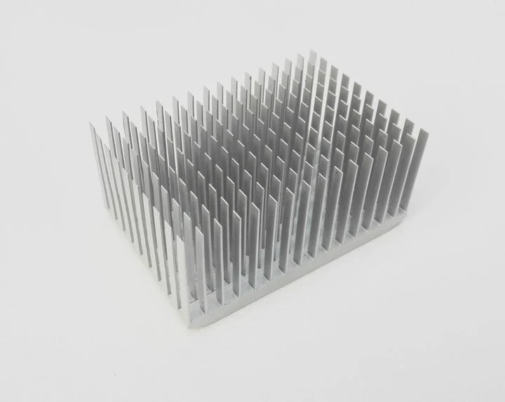
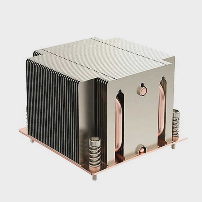
Yes. Vapor chamber can combine with traditional heat sinks. When properly matched, the vapor chamber spreads heat over its base. The heat sink fins then dissipate this heat into air or liquid. The two parts do what each does best — spread, then cool. This creates a strong cooling solution.
It helps to look at how to connect these parts well. Below we explore if merging them brings benefits, what limits exist, and how to make their interface efficient.
Can a Vapor Chamber be integrated with traditional heat sinks?
Many designers feel frustrated when a hot device has only a small cold‑plate. The hot spot does not spread. That hurts cooling. People worry their fins won’t cool evenly. Vapor chamber could solve that stress.
Yes. You can integrate a vapor chamber with a traditional heat sink. The vapor chamber acts as a flat, high‑conductivity plate. It spreads heat quickly over a wide area. Then you can place fin arrays or heat sink modules on top or around the vapor chamber. This integration works if the base area and mounting match.
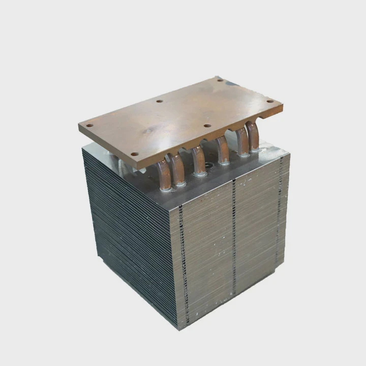
Many thermal systems already use metal bases or copper plates. Vapor chamber replaces those plates. It gives much better lateral thermal conduction. The fins or heat sink modules sit on top or attach through mechanical clamps. In electronic cooling, you could use a vapor chamber as a bridge between a hot chip and the fin stack. In liquid‑cooled modules, the vapor chamber base connects to a cold plate, and the external metal fins handle ambient air cooling.
One must check the base dimensions. The vapor chamber’s footprint must match the heat sink base or mount. Mechanical mounting must avoid stress that could warp or bend the chamber. Use flat surfaces and even pressure. Thermal interface material (TIM) should fill micro‑gaps between vapor chamber and fins. A thin, even TIM layer helps heat spread smoothly. If TIM is too thick or uneven, thermal resistance rises and benefits drop.
Because the vapor chamber can spread heat quickly, the entire fin array becomes effective. Then fins are no longer limited by the hot spot; they operate at lower thermal gradient and can cool a larger area. This integration applies widely: power electronics, CPU/GPU cooling, industrial converters, etc.
Does combining Vapor Chamber and fins improve overall cooling?
Many people feel unhappy when cooling seems weak for heavy heat load. Fins cool some, base plate spreads little. Heat stays hot spot. It leads to high temperature and poor reliability. Combining could fix that.
Yes. Combining a vapor chamber with fins usually improves total cooling performance. The vapor chamber spreads heat fast and evenly. The fins then dissipate that heat into air or liquid. The system cools more heat per time than base only or fins only.
When a device produces a lot of heat, the vapor chamber lowers the thermal gradient inside the base. Then fins get warmer base across a larger area. That helps fins dissipate heat faster. Also this lowers hotspot temperature. That improves reliability.
For example, if a chip puts out 150 W, a small base with limited lateral conduction might leave a 10 °C‑20 °C hotspot. With a vapor chamber, temperature spreads, so no local overheating. Fins around the chamber see more uniform heat flux. Then fins and airflow can remove more heat per second. The result is lower average temperature and smaller temperature difference across the device.
Another benefit is improved transient response. When heat load spikes, the vapor chamber absorbs heat and spreads it instantly. Fins then dissipate it gradually. This two‑stage process helps manage bursts of heat. That means the cooling system deals better with dynamic loads.
Sometimes a pure fin heat sink can saturate if the base is too small or conduction poor. Adding a vapor chamber removes that bottleneck. Then fins can perform to their full potential. The combined design often outperforms either part alone, especially under high heat load and airflow conditions.
Are there design constraints when coupling Vapor Chamber with heat sinks?
Many engineers assume combining is easy. They design a big fin array and drop a vapor chamber below. Then they test. Sometimes results are poor. They regret not checking constraints early.
Yes. There are several design constraints when combining vapor chamber with heat sinks. The footprint must match. Mechanical pressure must stay within limits. Thermal interface material must be thin and uniform. The vapor chamber internal structure must align. Fins must not block vapor flow. The whole stack must allow airflow or liquid flow.
Key constraints and risks
| Constraint | What can go wrong |
|---|---|
| Footprint mismatch | Poor contact. Uneven heat distribution. |
| Uneven pressure / warping | Chamber bends, leaks, or internal seal fails. |
| Thick or uneven TIM | High thermal resistance, lower performance. |
| Fins pressing on chamber surface | Block vapor flow, damage chamber. |
| Airflow obstruction | Fins or layout block airflow, reduce cooling. |
| Vibration / shock | Risks mechanical damage to chamber. |
The vapor chamber internal wick or fluid path must stay intact. If mounting clamps concentrate stress on one point, internal geometry can distort. That reduces the vapor chamber’s heat spreading ability. In the worst case, actual thermal resistance increases compared to a plain base. That defeats the purpose of combining.
The choice of thermal interface material (TIM) matters a lot. A thick gap filler or soft pad might be convenient mechanically. But high compressibility or uneven thickness means air gaps or low contact pressure. Both raise thermal resistance. Best is a thin, low‑resistance TIM. Use solder, thermal paste, or a high‑conductivity graphite pad with low thickness. Ensure even pressure over full area.
Airflow is another constraint. If fin arrangement blocks airflow or if the enclosure walls are too close, fins can’t dissipate heat effectively. The benefit of spreading heat with vapor chamber disappears. The fins must be placed so air can flow freely through them. That means design must consider space, fan placement, airflow channels, and clearance.
Also vibration or shock can cause long‑term issues. Fins add weight. The combined stack might be heavy. For portable devices or systems subject to vibrations, the mounting must be robust. Use proper brackets and avoid stress points. Also consider expansion due to temperature changes. Different materials expand differently. Use spring loaded clamps or flexible mounting to absorb differential expansion.
Because of these constraints, some designs fail. Engineers see worse thermal performance or mechanical failures. The key is to plan early. Check mechanical layout, footprint, airflow, TIM thickness, mounting pressure, vibration — all before final assembly. Then test prototypes under real conditions.
How to optimize interface between Vapor Chamber and heat sink structure?
Many designs stop at just sticking chamber under fins. That feels easy. They hope it works. But performance stays average. They start to doubt again. They wonder how to make it work best.
You can optimize interface by focusing on flatness, contact pressure, TIM selection, alignment, and airflow path. A flat, rigid base plate helps spread pressure. Thin, conductive TIM minimizes thermal resistance. Clamp pressure must be uniform. Fins must sit flush. Airflow must reach fins. This gives best cooling.
Checklist of interface optimization
- Ensure base plate or vapor chamber surface is flat within strict tolerance. Use milling or lapping if needed.
- Use thin, high‑conductivity TIM or solder between chamber and heat sink. Avoid thick gap fillers.
- Install uniform clamps or screws. Use torque specs to avoid warping.
- Align fins or heat sink modules precisely over chamber area. Avoid part of fins extending off chamber base.
- Design airflow to flow through fin array without obstruction. Leave clearance for intake and exhaust air or liquid flow.
- For vibration/shock: add rubber washers or spring clips to absorb stress. Consider thermal expansion.
Example layout options
| Layout Type | Best use case | Benefits |
|---|---|---|
| Vapor chamber base + fin stack on top | Air-cooled PC, industrial converters | Good for high heat with strong airflow |
| Vapor chamber base + fin modules around sides | Tight space or low-profile devices | Good when vertical space limited |
| Vapor chamber + cold plate + external fins | Hybrid air/liquid cooling | Offers flexibility and dual-stage cooling |
Often combining a vapor chamber with fins works best when the base is wide. The vapor chamber spreads heat so fins everywhere get similar heat load. Then fins cool more heat total. Uniform TIM and mounting pressure ensure no hot spot under the chamber.
In design phase select TIM carefully. Thermal paste is common. Graphite pads may help if space limited. Soldering gives lowest resistance but needs care. Use thin layer. After assembly test thermal resistance with real heat load and airflow. Check temperature distribution across fins and base. Use thermal camera if possible. That shows cold spots or uneven heating.
Also test under vibration or shock if device moves or subject to stress. Check for mechanical failure or leak in vapor chamber. Check thermal performance over time. That ensures the design stays stable.
Another point: consider expansion. Metals expand with heat. Vapor chamber, fins, base plate may use different materials. Use flexible mounting or spring clips to absorb expansion. That avoids stress on chamber body.
Finally choose fin orientation based on airflow direction. Align fins perpendicular to airflow for best cooling. If space limited, consider blowers or directed air through narrow channels. Avoid blocking air path with cables or other parts.
Conclusion
Combining a vapor chamber with a heat sink can give much better cooling than using either part alone. When footprint matches, interface is flat, TIM is thin and uniform, and airflow is good, the combined design spreads heat evenly and dissipates it efficiently. This delivers lower temperature and higher reliability for high‑heat devices.
TAGS
Latest Articles

Volume discount levels for heat sink orders?
Buyers often ask when heat sink prices start to drop with volume. Many worry they’re overpaying for small orders. This guide explains how B2B volume pricing works for thermal components. Heat sink
21 Dec,2025
Heat sink long-term supply contract options?
Many buyers want stable pricing and reliable delivery for heat sinks. But without a clear contract, risks grow over time. This article explores how to secure better long-term supply deals. Long-term
21 Dec,2025
Tooling cost for new heat sink profiles?
Many engineers struggle to understand why tooling for custom heat sinks costs so much. They worry about budgeting and production timelines. This article breaks down the cost drivers behind tooling.
21 Dec,2025
Heat sink custom sample process steps?
Sometimes, starting a custom heat sink project feels overwhelming—too many steps, too many unknowns, and too many risks. You want a sample, but not endless delays. The process for requesting and
20 Dec,2025
Standard B2B terms for heat sink payments?
When buyers and sellers in B2B heat sink markets talk about payment, many don’t fully understand what’s standard. This can lead to delayed orders, miscommunication, and even lost business
20 Dec,2025
Heat sink pricing factors for large orders?
Heat sinks are vital for many systems. When prices rise, projects stall and budgets break. This problem can hit teams hard without warning. Large order heat sink pricing depends on many factors. You
20 Dec,2025Related Articles
- Reliable bonding method for Vapor Chamber joints?
- How clean should Vapor Chamber surfaces be?
- Is Vapor Chamber suitable for mass production?
- Vapor Chamber documentation required for customs
- Import duty for Vapor Chamber in Germany?
- Vapor Chamber packaging moisture tests?
- Vapor Chamber for thermal cycling environments?
- Required energy evaluation for Vapor Chamber?
- Cost saving ideas for Vapor Chamber production?
- Vapor Chamber functional testing standards?
- Estimated lifespan of Vapor Chamber in industry?
- Vapor Chamber technical support availability?
Author
Dr. Emily Chen
Chief AI Researcher
Leading expert in thermal dynamics and AI optimization with over 15 years of experience in data center efficiency research.
Categories
Latest Products


Recommend Categories
- Liquid cooling plate Manufacturer
- Industrial Heat Sink Manufacturer
- Standard Heat Sink Manufacturer
- Aluminum Heat Sink Manufacturer
- Copper Heat Sink Manufacturer
- Anodized Heatsink Manufacturer
- Stamping heat sink Manufacturer
- Die Casting Heatsink Manufacturer
- Soldering heat sink Manufacturer
- CNC Parts Manufacturer
Latest Products
- Wholesale Aluminum Radiator
- Water Cooling Plate Kit
- Water Cooling Heat Sink
- Water Cooling Heat Sink Kit
- Stainless Steel Water Distributor
- Server Water Cooling Plate Kit
- Server Liquid Cooling System
- Server Aluminum Cooling Kit
- S19 Full Cover Cooling Plate
- S19 Cooling Plate Kit
- S19 Aluminum Cooling Plate
Contact Expert
Have questions about this article? Reach out to our experts directly.