Best geometry for compact heat sink?
I once saw many heat sink designs that wasted space or air. A smart shape can fix that and cut size without losing cooling power.
The best geometry makes fins and flow channels tight but not cramped. It balances surface area, air path, and space efficiency for strong cooling in small volume.
A few good shapes and design tactics help build compact but effective heat sinks.
What shapes optimize space and heat dissipation?
Good shape design can give lots of surface area while keeping a small footprint. The shape of fins, base, and overall stack matters for compact, high‑performance sinks.
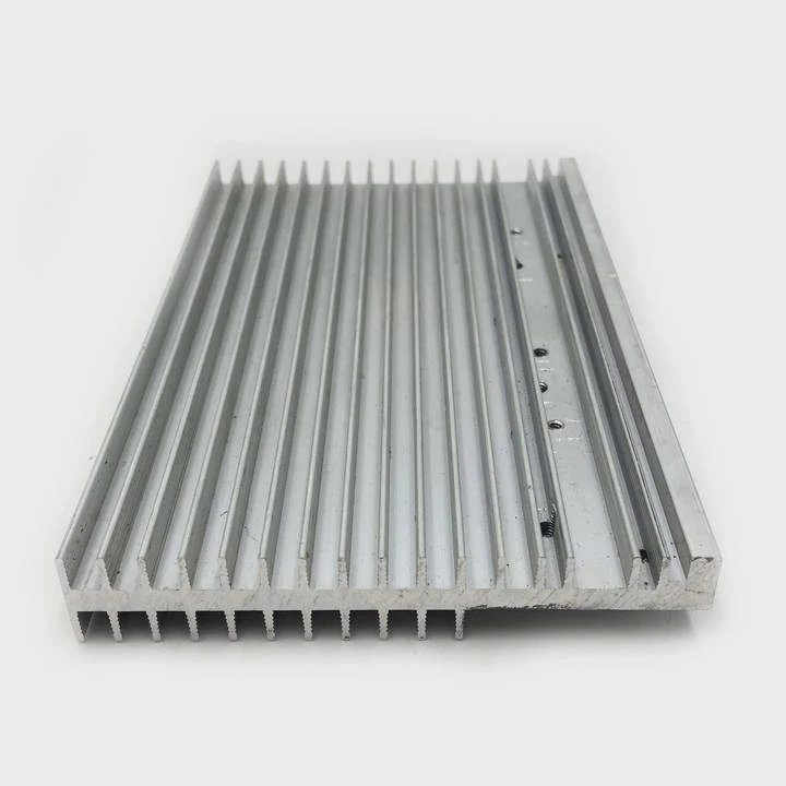
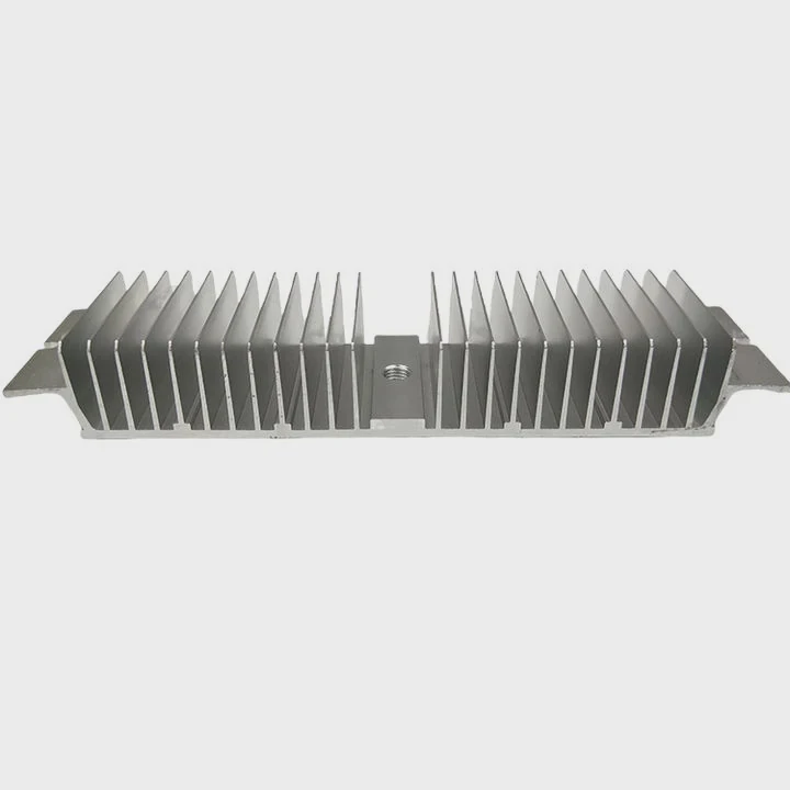
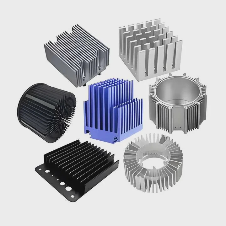
Shapes like dense vertical fins, folded plate fins, pin‑fins, and stacked microchannels often give high surface area per volume. They squeeze cooling power into small spaces.
To pick a good shape you match the heat load, space limits, and airflow path. Some shapes use tall narrow fins if air flow is strong. Others use many thin fins or pins if air moves slowly. Some designs use waves or zigzag fins to increase turbulence. That boosts heat transfer but still keeps a small size.
| Shape type | Best for | Strength / Benefit |
|---|---|---|
| Vertical straight fins | Good airflow, simple flow path | High surface area, easy to manufacture |
| Pin‑fin array (cylinders or small rods) | Limited space & multi‑directional airflow | Compact, isotropic airflow capability |
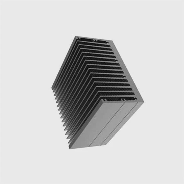
| Folded / zigzag plate fins | Moderate flow, limited height | High fin surface per volume, compact height |
| Micro‑channel stack | Very high heat flux, liquid or high‑pressure air | Very high surface density, compact volume |
Each shape balances different needs. For example, pin‑fins work when air can come from many directions. Micro‑channels fit when space is tight but air pressure or flow is high. Folded fins compress vertical height. Straight fins deliver best heat conduction if airflow aligns.
In practice many compact heat sinks use combinations — like pin‑fins near base, straight fins further up. That gives good conduction and good airflow. Design also must consider manufacturing cost, fin thickness, and ease of cleaning or dust removal.
How does geometry affect airflow distribution?
Geometry does more than give surface area. It guides air. Where fins or channels sit, how they orient, and how dense they are all steer how air flows. Bad geometry can choke airflow or leave dead zones. Good geometry spreads flow evenly so every fin carries heat away.
When fins are too dense and parallel, air may flow only near front and bypass middle. When fins are angled or staggered, airflow may weave between them, hitting more surfaces. When channels are narrow and uniform, flow may go straight but slow. When channels vary or are curved, flow may swirl and touch more surfaces, improving cooling.
Flow path length matters too. If air must bend or turn sharply, pressure drop rises. That can reduce flow speed. Compact designs sometimes pack fins tightly — that raises resistance. That kills airflow. Good geometry avoids sharp turns and sudden narrowing. It gives smooth path from intake to exhaust.
Here are typical geometry impacts on airflow:
- Straight fins aligned with airflow — best when airflow is strong and direct. Air moves cleanly through, minimal loss, good conduction.
- Staggered or offset fins/pins — help distribute airflow, avoid channeling, hit more surfaces. Good when flow is moderate or multi‑directional.
- Dense fin spacing — increases surface area, but must be paired with sufficient pressure or spacing to avoid choking.
- Variable spacing or tapered fins — near intake fins spaced wider, then denser deeper inside. That spreads flow and avoids dead zones.
- Curved or wavy fins — create turbulence, which raises heat transfer by mixing boundary air layers. That helps when flow speed is low.
In many real cooling systems, airflow is not uniform. Cables, boards, obstacles shift air path. Good geometry works even with messy air flow. That often means using pin‑fins or staggered arrays instead of strict straight fins.
Thus geometry affects not just how much surface you have — it shapes where air goes, how fast, and how evenly across the sink. Poor geometry kills cooling even with good fin area.
Can 3D printing improve compact heat sink design?
3D printing opens new geometry that old methods cannot make. It lets us make complex fins, internal channels, thin walls, and integrated structures. That can shrink size and boost cooling.
3D printing (additive manufacturing) can produce complex, high‑surface, lightweight heat sinks. It allows shapes like internal lattice, curved fins, or integrated ducts that give good cooling in tight spaces.
Additive manufacturing (AM) frees design from straight fins or simple plates. You can build pin‑fins, lattices, gyroid structures, micro‑channels — all in one block. That yields high surface density. You save volume because AM can avoid wasted material, and integrate mounting parts, screw bosses, ducts in one part. That reduces assembly size.
Also AM can vary fin thickness. Near hot base fins are thick for good conduction. Near tips fins are thin to increase surface area. Traditional milling cannot make such varied geometry easily. AM can.
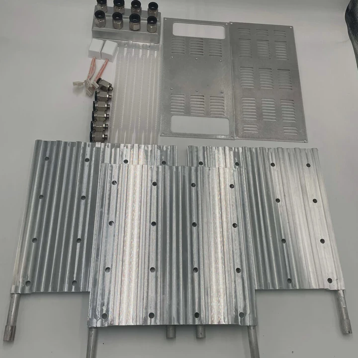
Another benefit is internal ducting. You can embed narrow passages or entire fluid channels inside a block. For liquid cooling or forced air, that boosts heat removal without external parts. For example, a heat sink can have a base that spreads heat, internal channels that carry coolant, and external fins that dump heat — all printed together. That saves space and improves reliability.
But AM also has drawbacks. Printed metal parts may have lower thermal conductivity because of internal porosity or surface roughness. Surface finish matters. If fins are rough, airflow friction rises. That can cut flow, offsetting gains. Printer resolution limits minimal fin thickness or spacing. Too thin and fins may warp or break.
Material choice also matters. Common 3D printing metals (like aluminum alloys or stainless steel) may not match thermal conductivity of pure metals. Designers must balance conductivity, strength, and printability.
In short, 3D printing improves compact heat sink design when you need complex geometry, small volume, or integrated parts. You must take care of material quality, finishing, and flow design to get real cooling benefit.
What CAD tools aid compact geometry modeling?
Good geometry starts in design software. CAD tools help create, test, and optimize complex heat sink shapes before manufacturing. The right tools make compact design faster and more reliable.
CAD tools with parametric design, simulation, and support for complex geometry help model compact heat sinks. Tools like parametric CAD, CFD simulators, and lattice‑generator plugins speed design and validation.
Here are some common CAD tools and what they offer:
| Tool / Feature | What it helps with |
|---|---|
| Parametric CAD (like Autodesk Fusion, SolidWorks, Creo) | Easily change fin count, spacing, orientation — test many versions fast |
| Lattice or topology‑optimization tools | Generate efficient internal structure, lattice fins, or micro‑channels |
| CFD (Computational Fluid Dynamics) modules / plugins | Simulate airflow through fins and ducts before building |
| Thermal‑stress simulators | Check if fins or structure bend or fail due to heat or mounting stress |
| Built‑in 3D printing preparation tools | Check for overhangs, wall thickness, support needs for printed parts |
With parametric CAD, one can build a base geometry then adjust fin density or spacing. That lets designers test many shapes fast. That saves time when trying to shrink size but keep performance.
Topology tools help when shape is not regular. For example, a lattice that follows heat flow path. Or micro‑channels that curve around hotspots. Those tools create geometry that human designer might miss.
CFD simulations are key. They show how air flows through fins, where air may bypass, where pressure drop is high. They let designers change spacing, orientation, duct placement before building. That avoids expensive prototypes.
Thermal‑stress tools check if fins will bend or warp from heat cycles or vibration. For compact heat sinks, thin fins and dense arrays are common. They can fail under stress. Simulation helps catch that early.
Finally, 3D print preparation tools check if design can be printed. They warn if fins are too thin, overhangs need supports, or parts are weak. That is key when geometry is complex.
When I design a compact sink, I start in parametric CAD. Then I run CFD to test airflow. Then I use thermal simulation to see heat flow. When all looks good I either print or prototype with machining. This workflow cuts time and avoids mistakes.
Conclusion
Smart geometry matters more than raw size. Dense fins, pin arrays, folded shapes, and internal channels can give small heat sinks big cooling power. Air path and spacing shape actual performance. 3D printing and modern CAD let us build complex, compact designs with confidence. A well‑designed geometry often cools better while saving space.
TAGS
Latest Articles

Volume discount levels for heat sink orders?
Buyers often ask when heat sink prices start to drop with volume. Many worry they’re overpaying for small orders. This guide explains how B2B volume pricing works for thermal components. Heat sink
21 Dec,2025
Heat sink long-term supply contract options?
Many buyers want stable pricing and reliable delivery for heat sinks. But without a clear contract, risks grow over time. This article explores how to secure better long-term supply deals. Long-term
21 Dec,2025
Tooling cost for new heat sink profiles?
Many engineers struggle to understand why tooling for custom heat sinks costs so much. They worry about budgeting and production timelines. This article breaks down the cost drivers behind tooling.
21 Dec,2025
Heat sink custom sample process steps?
Sometimes, starting a custom heat sink project feels overwhelming—too many steps, too many unknowns, and too many risks. You want a sample, but not endless delays. The process for requesting and
20 Dec,2025
Standard B2B terms for heat sink payments?
When buyers and sellers in B2B heat sink markets talk about payment, many don’t fully understand what’s standard. This can lead to delayed orders, miscommunication, and even lost business
20 Dec,2025
Heat sink pricing factors for large orders?
Heat sinks are vital for many systems. When prices rise, projects stall and budgets break. This problem can hit teams hard without warning. Large order heat sink pricing depends on many factors. You
20 Dec,2025Related Articles
- Heat sink airflow needs for cooling systems?
- Strongest material option for heat sink design?
- Can heat sink support heavy thermal loads?
- Minimum flatness needed for heat sink bases?
- Required tolerance for machined heat sink?
- What alloy is best for heat sink extrusion?
- Heat sink options for automotive electronics?
- Heat sink solutions for telecom base stations?
- Suitable heat sink for EV battery packs?
- Industrial automation devices needing heat sink?
- Renewable energy inverters requiring heat sink?
- Heat sink performance in medical equipment?
Author
Dr. Emily Chen
Chief AI Researcher
Leading expert in thermal dynamics and AI optimization with over 15 years of experience in data center efficiency research.
Categories
Latest Products


Recommend Categories
- Liquid cooling plate Manufacturer
- Industrial Heat Sink Manufacturer
- Standard Heat Sink Manufacturer
- Aluminum Heat Sink Manufacturer
- Copper Heat Sink Manufacturer
- Anodized Heatsink Manufacturer
- Stamping heat sink Manufacturer
- Die Casting Heatsink Manufacturer
- Soldering heat sink Manufacturer
- CNC Parts Manufacturer
Latest Products
- Wholesale Aluminum Radiator
- Water Cooling Plate Kit
- Water Cooling Heat Sink
- Water Cooling Heat Sink Kit
- Stainless Steel Water Distributor
- Server Water Cooling Plate Kit
- Server Liquid Cooling System
- Server Aluminum Cooling Kit
- S19 Full Cover Cooling Plate
- S19 Cooling Plate Kit
- S19 Aluminum Cooling Plate
Contact Expert
Have questions about this article? Reach out to our experts directly.