Vapor Chamber 3D modeling guidelines?
Vapor chamber modeling can be confusing. Designers ask how much detail to include, how to model the wick or fluid, and whether manufacturing limits apply. Wrong models may mislead simulations or cause production issues.
To model a vapor chamber in 3D, you must follow specific guidelines — including geometry simplifications, material definitions, and boundary conditions — to reflect real-world thermal and structural behavior.
It is not just about shapes. Good modeling helps avoid design errors. Below, I walk through the four most asked questions about 3D modeling vapor chambers, especially for CAD and simulation use.
What guidelines apply when 3D modelling a Vapor Chamber?
Designers often use the same modeling methods as for solid metals. This leads to thermal errors. Some skip fluid regions or internal structures. Others overcomplicate geometry. This creates confusion or slow CAD performance.
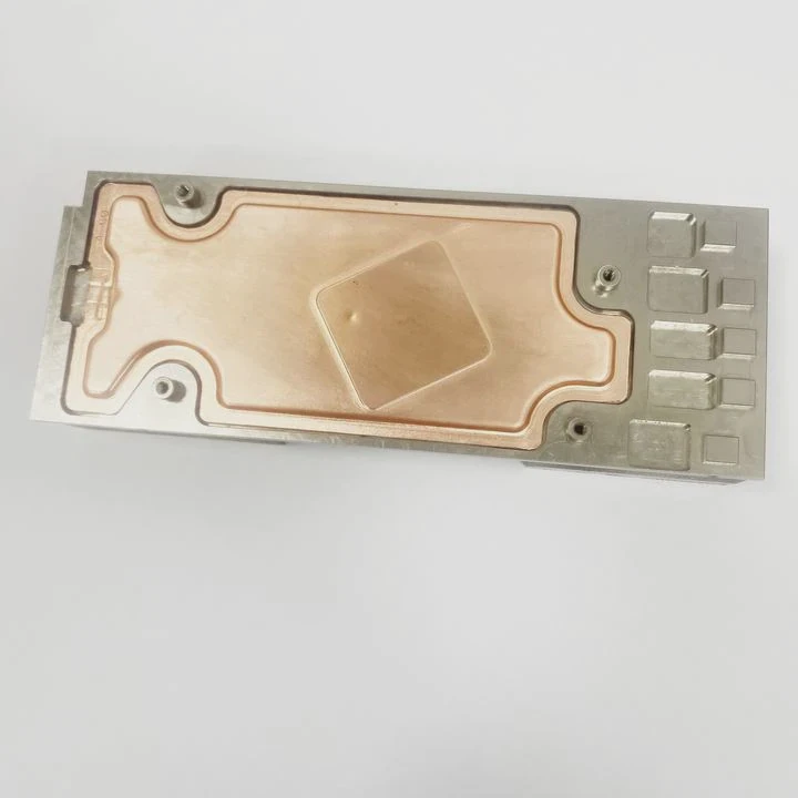
The main guideline is: simplify geometry but preserve thermal paths. Model key layers — wall, wick, cavity — and assign correct material properties for simulation accuracy.
Modeling a vapor chamber is different from modeling a solid copper block. Though the external shape might look similar, the inside functions by phase change — evaporation and condensation — not simple conduction. This calls for abstracted layers in 3D models, especially for thermal simulations.
Basic Guidelines for 3D Modeling
| Element | Modeling Tip |
|---|---|
| Outer walls | Model as solid shell, usually copper or aluminum |
| Wick layer | Use thin solid layer with porous material property |
| Vapor cavity | Model as a central volume or as simplified thermal layer |
| Working fluid | Do not model individual droplets; use effective thermal conductivity |
| Bonding or contact pads | Include for contact resistance representation |
| Ports / fill holes | Omit unless needed for manufacturing drawing |
| Internal structure detail | Simplify or abstract — do not model individual grooves or mesh |
In most CAD and FEA tools, vapor chambers are best treated as multi-layer composites. Thermal simulations should assign an effective thermal conductivity (e.g. 2000–5000 W/m·K) to the central vapor chamber volume. Some models separate wick, wall, and vapor zones. Others treat the chamber as a single high-conductivity body.
Do not include excessive internal detail — this clutters the model and slows down computation without improving accuracy. Also, many tools cannot resolve phase-change unless using CFD (computational fluid dynamics). For most product design teams, using equivalent material properties and simplified internal geometry is more practical.
Should the wick structure be included in the 3D model?
The wick is the engine of the vapor chamber. Designers may ask whether it needs full modeling. Mesh? Grooves? Sinters? But this detail can overload the model and slow simulations.
No — the wick is not modeled in full geometric detail. Instead, it’s abstracted as a thin porous layer or included in the overall thermal conductivity of the vapor chamber.
Wick structures are very fine and intricate. They include sintered powder, grooved copper, screen mesh, or fiber wicks. These structures help move liquid from condenser back to evaporator regions via capillary action. The geometry is often smaller than 0.5 mm, with many micro pores.
Trying to model these features in 3D is not practical. Instead, good modeling practice is to include the wick as either:
- A thin porous solid layer (e.g. 0.3 mm thick) with lower thermal conductivity, or
- An effective thermal property inside the whole vapor chamber core
Wick Modeling Comparison
| Approach | Pros | Cons |
|---|---|---|
| Full geometric mesh | Accurate shape | Very heavy, slows simulation |
| Thin porous solid layer | Easy to manage, semi-accurate | May miss fine capillary effects |
| Effective thermal property | Simplified, works for most design | No separate wick behavior modeled |
In FEA tools (like Ansys, COMSOL, SolidWorks), the wick can be modeled using porous media definitions if detailed fluid modeling is needed. Otherwise, in general-purpose simulations, a high-efficiency conduction assumption is acceptable for steady-state thermal performance.
Also, many manufacturers do not disclose wick geometry exactly, as it is often proprietary. So modeling based on assumptions may not be accurate. It is better to request the equivalent thermal conductivity from the vendor and apply it to the chamber core in your simulation.
Do manufacturing constraints impact the 3D model geometry?
Some designs fail in production because they are modeled for ideal shapes. Real vapor chambers face limits in thickness, bending, and weld zones. Ignoring these leads to rework or part rejection.
Yes — manufacturing constraints such as minimum thickness, bending radii, and weld seam locations must be considered during 3D modeling to ensure the design can be fabricated.
Key Manufacturing Limits to Include
| Constraint Type | Design Limit / Rule |
|---|---|
| Minimum wall thickness | Typically ≥ 0.3 mm for copper shells |
| Chamber total thickness | ≥ 1.5 mm preferred (depends on process) |
| Bending radius | ≥ 2× material thickness to avoid cracks |
| Laser weld area | Requires flat, accessible seam perimeter |
| Fill tube location | Keep accessible on flat surface if required |
| Edge sealing zone | Avoid critical features near outermost edges |
These constraints help prevent problems like:
- Chamber bursting during evacuation or charging
- Poor weld quality due to sharp corners
- Deformation under pressure due to thin walls
- Inaccessibility of fill tube during fluid fill process
Some 3D designs also include mounting tabs, screw holes, or cutouts. These features should not intersect the main vapor region. Cutouts can disrupt vapor flow and reduce efficiency. The core region should be thermally and structurally clean.
Practical Advice
- Before finalizing a 3D design, check with manufacturing teams for DFM rules.
- Use standard thickness ranges (e.g. 1.5–3.0 mm) for predictable performance.
- Place fill tubes and weld seams away from mounting holes or high-stress zones.
- Provide 2D section drawings with tolerances and sealed region markings.
Is the working fluid region modelled in the 3D design?
Some designers want to show internal fluids for simulation. Others ignore them entirely. This creates confusion about how thermal resistance and mass transfer are represented in the model.
No — the working fluid is not modeled as a liquid or gas in normal 3D design. Its thermal effects are represented using effective thermal conductivity in the vapor chamber core.
Working fluid — usually water, alcohol, or refrigerant — exists inside the vapor chamber as both liquid and vapor. The amount is small and sealed. It moves via evaporation at the hot side and condenses at the cold side, enabling two-phase heat transport.
Trying to model this directly requires CFD tools with phase-change physics — not typical for most product designers.
Instead, the vapor region is assigned a bulk effective thermal conductivity, often in the range of:
- 2000–5000 W/m·K for high-performance flat vapor chambers
- 1500–3000 W/m·K for hybrid or low-profile designs
These values reflect the net heat transfer efficiency of phase change. This includes:
- Wick resistance
- Vapor transport delay
- Condensation resistance
- Shell thermal losses
So the fluid is not shown as a region. It is part of the combined thermal model. You define this in FEA tools using custom material properties or thermal resistance networks.
What to Do in Simulation
- Create a central body for the vapor chamber core
- Assign an effective isotropic or anisotropic thermal conductivity
- Do not define separate vapor or fluid zones
- Use steady-state or transient thermal simulations (not CFD)
This method balances accuracy and speed. Unless you’re designing the vapor chamber itself (not just using it), there is no need to model fluid directly.
Conclusion
3D modeling of vapor chambers requires balance. The design must reflect real thermal behavior without overcomplicating geometry. Wick and fluid zones are best abstracted. Manufacturing limits must guide shapes and thickness. Using simplified but smart models saves time, avoids errors, and improves accuracy.
TAGS
Latest Articles

Volume discount levels for heat sink orders?
Buyers often ask when heat sink prices start to drop with volume. Many worry they’re overpaying for small orders. This guide explains how B2B volume pricing works for thermal components. Heat sink
21 Dec,2025
Heat sink long-term supply contract options?
Many buyers want stable pricing and reliable delivery for heat sinks. But without a clear contract, risks grow over time. This article explores how to secure better long-term supply deals. Long-term
21 Dec,2025
Tooling cost for new heat sink profiles?
Many engineers struggle to understand why tooling for custom heat sinks costs so much. They worry about budgeting and production timelines. This article breaks down the cost drivers behind tooling.
21 Dec,2025
Heat sink custom sample process steps?
Sometimes, starting a custom heat sink project feels overwhelming—too many steps, too many unknowns, and too many risks. You want a sample, but not endless delays. The process for requesting and
20 Dec,2025
Standard B2B terms for heat sink payments?
When buyers and sellers in B2B heat sink markets talk about payment, many don’t fully understand what’s standard. This can lead to delayed orders, miscommunication, and even lost business
20 Dec,2025
Heat sink pricing factors for large orders?
Heat sinks are vital for many systems. When prices rise, projects stall and budgets break. This problem can hit teams hard without warning. Large order heat sink pricing depends on many factors. You
20 Dec,2025Related Articles
- How to calculate Vapor Chamber efficiency?
- Vapor Chamber REACH analysis documentation?
- Vapor Chamber import regulations in USA?
- Does Vapor Chamber meet aerospace standards?
- Vapor Chamber industry certification list?
- Vapor Chamber failure analysis methods?
- Are there patented Vapor Chamber designs?
- How to optimize Vapor Chamber mass production?
- Standard cost of Vapor Chamber tooling?
- Can Vapor Chamber be welded?
- Vapor Chamber requirements for CE marking?
- Best simulation software for Vapor Chamber?
Author
Dr. Emily Chen
Chief AI Researcher
Leading expert in thermal dynamics and AI optimization with over 15 years of experience in data center efficiency research.
Categories
Latest Products


Recommend Categories
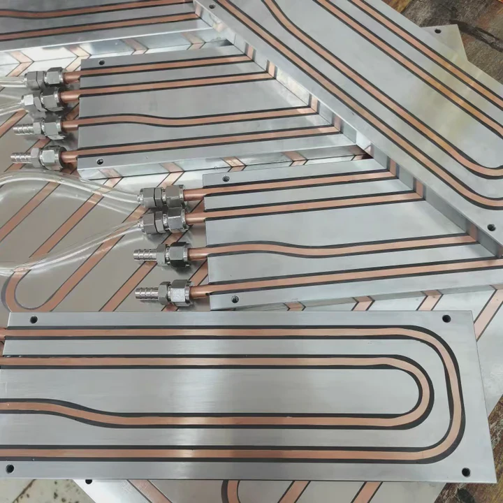
- Liquid cooling plate Manufacturer
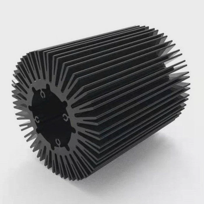
- Industrial Heat Sink Manufacturer
- Standard Heat Sink Manufacturer
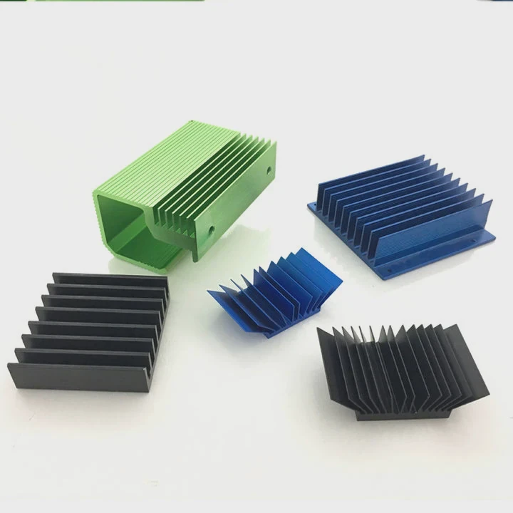
- Aluminum Heat Sink Manufacturer
- Copper Heat Sink Manufacturer
- Anodized Heatsink Manufacturer
- Stamping heat sink Manufacturer
- Die Casting Heatsink Manufacturer
- Soldering heat sink Manufacturer
- CNC Parts Manufacturer
Latest Products
- Wholesale Aluminum Radiator
- Water Cooling Plate Kit
- Water Cooling Heat Sink
- Water Cooling Heat Sink Kit
- Stainless Steel Water Distributor
- Server Water Cooling Plate Kit
- Server Liquid Cooling System
- Server Aluminum Cooling Kit
- S19 Full Cover Cooling Plate
- S19 Cooling Plate Kit
- S19 Aluminum Cooling Plate
Contact Expert
Have questions about this article? Reach out to our experts directly.